Time‑Depth Conversion — A Complete Overview
Time‑Depth Conversion — A Complete Overview
Introduction
Seismic data is recorded in time, but the subsurface exists in depth. Bridging that gap is one of the most important steps in seismic interpretation. Time‑depth conversion (TDC) transforms seismic reflections from two‑way travel time (TWT) into true geological depth, enabling accurate structural mapping, reservoir modeling, and well planning.
This article explains why time‑depth conversion matters, how it works, and the methods used across the industry.
1. What Is Time‑Depth Conversion?
Time‑depth conversion is the process of transforming seismic reflection times into depth measurements using velocity information. Because seismic waves travel at different speeds through different rocks, velocity models are essential for accurate conversion.
TDC is used for:
Structural mapping
Depth‑based reservoir models
Well planning and geosteering
Volumetric calculations
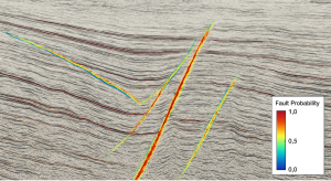
Fault and horizon depth estimation
2. Why Time‑Depth Conversion Matters
Seismic data in time can be misleading. A structure that appears high in time may be low in depth if velocities vary significantly.
Without proper conversion, interpreters risk:
Misplaced wells
Incorrect reservoir thickness
Fault misinterpretation
Poor volumetric estimates
Accurate TDC reduces uncertainty and improves decision‑making.
3. Inputs Required for Time‑Depth Conversion
A. Seismic Horizons
Picked reflectors in time.
B. Well Data
Checkshots
VSP (Vertical Seismic Profile)
Sonic logs
C. Velocity Models
RMS velocity
Interval velocity
Layered models
Anisotropic models
D. Geological Constraints
Stratigraphic boundaries
Fault geometries
Basin trends
4. Time‑Depth Conversion Methods
A. Constant Velocity Conversion
The simplest method — rarely used except for quick checks. Pros: Fast Cons: Inaccurate for real geology
B. Layer Cake Models
Assume horizontal layers with constant velocities. Pros: Good for simple geology Cons: Poor for faulted or dipping structures
C. Well‑Tied Velocity Models
Use checkshots and sonic logs to calibrate seismic velocities. Pros: High accuracy near wells Cons: Limited away from well control
D. Horizon‑Based Conversion
Each horizon is converted using its own velocity field. Pros: Flexible Cons: Requires careful QC
E. Full 3D Velocity Models
Use:
Tomography
Migration velocities
Anisotropic models
Pros: Most accurate Cons: Computationally intensive
5. Challenges in Time‑Depth Conversion
Velocity Uncertainty
Small velocity errors can lead to large depth errors.
Lateral Velocity Variations
Salt bodies, carbonates, and channel systems complicate conversion.
Anisotropy
Velocities vary with direction, requiring advanced modeling.
Sparse Well Control
Limited calibration increases uncertainty.
6. Best Practices
Tie seismic to wells early
Validate velocities with multiple sources
Use anisotropic models when needed
Perform uncertainty analysis
Update models as new wells are drilled
Conclusion
Time‑depth conversion is essential for accurate subsurface understanding. By integrating seismic, well data, and velocity modeling, interpreters can produce reliable depth maps that support exploration and development decisions.